Reverse engineering a printed circuit board (PCB) is the process of taking an existing board and creating a schematic diagram and a bill of materials (BOM) for it. This process is useful when the original design files are unavailable or incomplete, and the board needs to be replicated, repaired, or modified.
A circuit board Bill of Materials (BOM) is a comprehensive list of all the components that are required to assemble a particular printed circuit board (PCB). This list is a vital part of the design process and ensures that the PCB is assembled accurately, and to the desired specification.
The circuit board BOM contains information about the components' specifications, quantities, and suppliers. It is the backbone of the manufacturing process, as it guides the procurement of all the components required to build the PCB.
A circuit board top view drawing is an important technical document that provides a detailed and comprehensive layout of the circuit board components from a top-down perspective. It is a critical component of the electronics manufacturing process and plays a crucial role in ensuring the accuracy and efficiency of the final product. In this article, we will discuss the basics of circuit board top view drawing and its importance in the electronics manufacturing industry.
Circuit board assembly drawing is a critical component of the electronics manufacturing process. It is an essential part of the product design and development cycle, and it helps ensure the accuracy, efficiency, and quality of the final product. In this article, we will discuss the basics of circuit board assembly drawing and its importance in the electronics manufacturing industry.
The printed circuit board (PCB) is an essential component of modern electronic devices, providing the foundation for the circuitry that makes these devices work. But creating a PCB is more than just designing a circuit diagram; it requires careful consideration of the physical layout of the components and the board itself. This is where the circuit board mechanical drawing comes in.
A circuit board mechanical drawing, also known as a PCB mechanical drawing or PCB layout, is a detailed plan or diagram that specifies the physical layout of components, connectors, and other elements on a PCB. This drawing shows the dimensions, placement, and orientation of each component, as well as the size and location of the board itself. It is an essential part of the design process for electronic devices, as it ensures that the PCB can be manufactured correctly and that the components will fit properly.
Gears play an essential role in various mechanical applications, from small machines to large industrial machinery. The automotive industry is one of the areas where gears are extensively used, where they play a vital role in transmitting power from the engine to the wheels. The design of a gear is critical as it affects the performance and efficiency of the system. In this article, we will discuss the design process of a gear with 105 teeth, a pressure degree of 20 degrees, and a module of 2, which is used in an automotive application.
Here is an example of how to add Anycubic 3D printers profiles to Cura software. Follow the below procedure to add the settings.
Here we listed most of Anycubic 3D printers Cura software profiles. These profiles are used with Cura software for a better 3D printing. The profiles are standard manufacturer profiles that are tested and compatible with this 3D printer listed below. However, these profiles are the printing settings, so please make sure other factors set up well, such as the bed levelling.
Here you will find the Anycubic Chiron profiles and settings for Cura software. These settings are tested for ABS, TPU and PLA. These settings have manufacturer recommended settings for speed, bed heat, nozzle heat etc. Follow the below procedure, and add the printer and the profiles. See how it prints, please share your feedback here.
Most users complain about print failures on Anycubic 4 Max Pro 2.0. Not sticking to bed, and many other problems. That is because of the lack of standard manufacturer standard profiles for this printer. Print failure has many reasons, by using the anycubic manufacturer standard profiles these issues will be resolved. Here, The ANYCUBIC standard profiles are attached with this page for CURA software for ANYCUBIC 4 Max Pro 2.0 FDM 3D Printer.
Electrovo specializing in a comprehensive range of CAD services, that is suitable for a range of applications and industries. From 3D modelling, engineering, mechanical, medical, we are able to offer you the CAD design that fulfils your need. We are fully equipped with the newest computer-aided CAD, circuit design and analysis software package. Our engineering laboratory is well equipped with a set of up-to-date equipment, programming devices and software package development tools and as well as environmental and testing instrumentation.
Stereolithography (SLA or SL; also known as stereolithography apparatus, optical fabrication, photo-solidification, or resin printing) is a form of 3D printing technology used for creating models, prototypes, patterns, and production parts in a layer by layer fashion using photochemical processes by which light causes chemical monomers and oligomers to cross-link together to form polymers.
Fused deposition modelling (FDM), also known as Fused filament fabrication (FFF), or called filament freeform fabrication, is a process of 3D printing that uses a continuous filament of a thermoplastic material.
This method describes the unbricking Samsung Galaxy Gear S3 SM-R765A watch. This method works for all Samsung Gear Watches, but the firmware will only work for the SM-R765A model of watch.
When the Samsung Gear watch is bricked so they will not turn on or function as a normal watch. This can be due to many reasons, as updating watch, software crash and many more.
To fix this issue the watch has to be connected to a computer and flash the updated firmware. To do this there is a need to have the access to the boot menu and the "Download Wireless" mode.
A smart power supply built from a computer power supply. Uses a microcontroller to control the output voltage. Consist of dual output and dual measurement metres. Just with 3 button turn on the power supply, switch the output power, hold and release the output power. With its safety features that allow you to hold the power so you can adjust the output power makes this power supply a better option between other DIY power supplies. Measure current, and volt for two different output. Two USB output for USB charging and USB power usage.
A relay module is a set of components that is electrically operated and works based on a signal. That can be connected to an Arduino or a transistor and or any other application that the output is a signal or a voltage. Same as relay the relay module is used to control high voltage electronic devices. A Relay module is a mechanical switch which is electrically operated by an electromagnet. When the electromagnet is activated with a low voltage, that can be 5 v, 12 v, 32 v, … it will triggers a mechanical arm that pulls a contact to make a connection between two contacts. Relay modules are used for high voltage controls, and big loads. Relay modules has low power lose in a circuit. In other hands they are slow and they are not quick as transistors.
The millimetre (international spelling as used by the International Bureau of Weights and Measures; SI unit symbol mm) or millimeter (American spelling) is a unit of length in the metric system, equal to one thousandth of a metre, which is the SI base unit of length. Therefore, there are one thousand millimetres in a metre. There are ten millimetres in a centimetre.
The millimetre (international spelling as used by the International Bureau of Weights and Measures; SI unit symbol mm) or millimeter (American spelling) is a unit of length in the metric system, equal to one thousandth of a metre, which is the SI base unit of length. Therefore, there are one thousand millimetres in a metre. There are ten millimetres in a centimetre.
One millimetre is equal to 1000 micrometres or 1000000 nanometres. Since an inch is officially defined as exactly 25.4 millimetres, a millimetre is therfore equal to exactly 5⁄127 (≈ 0.03937) of an inch.
A centimetre (international spelling as used by the International Bureau of Weights and Measures; symbol cm) or centimeter (American spelling) is a unit of length in the metric system, equal to one hundredth of a metre, centi being the SI prefix for a factor of 1/100.[1] The centimetre was the base unit of length in the now deprecated centimetre–gram–second (CGS) system of units.
Though for many physical quantities, SI prefixes for factors of 103—like milli- and kilo-—are often preferred by technicians, the centimetre remains a practical unit of length for many everyday measurements. A centimetre is approximately the width of the fingernail of an average adult person
Arduino is an open-source hardware and software company, project and user community that designs and manufactures single-board microcontrollers and microcontroller kits for building digital devices.
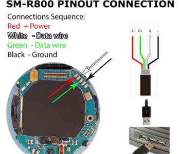
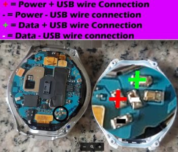
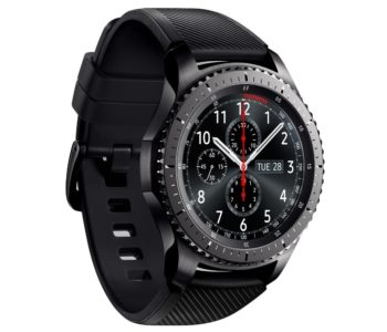
Here is the pin-out diagram drawing of Samsung Galaxy Watch Model SM-R800. Although all Samsung Products are coming with a USB cable connectivity with computers, so you can flash your device with firmware and reset it to factory setting. But unfortunately Samsung Watches doesn't not come with such ability. In most of these watches user need to connect the watch by a wireless connection. And it does need a computer with wireless connectivity. Well sometimes your wireless connection might break or your watch get bricked and you will have no way to connect your watch by a wireless connection.
Here is the Samsung Gear S2 3G SM-R730T PINOUTS diagram for those who wants to solder a usb wire into their watch. This is when your watch download wireless mode is not available and its bricked.
Guide to Connecting a Samsung Gear S2 and S3 Device Using Wi-Fi
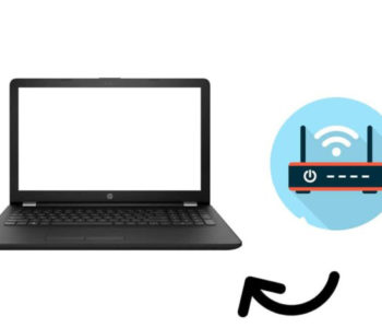
Here you will learn how to connect a Samsung Gear S2 and S3 watch to a Host computer by your local wifi Wi-Fi Connection or by a wire.
You will need to have a computer, a router or access point and your watch as described in this figure 1
By this method you will be able to put your watch into download mode and install firmwares by wires that you will need to solder inside your watch.
In case your watch keeps rebooting over and over and then dies, or you can't connect over wifi/bluetooth connection or you had an update and crashed your watch, so here is the method used to fix that problem.
Finally Samsung Gear S3 reactivation lock got unlocked. And there is way to reset reactivation of Samsung Gear Watches. Below is the method used for this purpose. This solution will help to reactivate a locked google account of watch. You need to download a Combination , and Firmware files and some other files used for this method.


