Relay module DIY Reverse Engineering
This article shows how to make Relay Module that can be used for Arduino and other applications such as circuit boards and other DIY projects. With this tutorial you will be able to make a relay module yourself.
So what is relay? A relay is an electrically operated switch. It consists of a set of input terminals for a single or multiple control signals, and a set of operating contact terminals. The switch may have any number of contacts in multiple contact forms, such as make contacts, break contacts, or combinations thereof.
Relays are used where it is necessary to control a circuit by an independent low-power signal, or where several circuits must be controlled by one signal. Relays were first used in long-distance telegraph circuits as signal repeaters: they refresh the signal coming in from one circuit by transmitting it on another circuit. Relays were used extensively in telephone exchanges and early computers to perform logical operations.

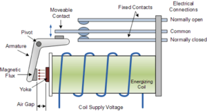
The traditional form of a relay uses an electromagnet to close or open the contacts, but other operating principles have been invented, such as in solid-state relays which use semiconductor properties for control without relying on moving parts. Relays with calibrated operating characteristics and sometimes multiple operating coils are used to protect electrical circuits from overload or faults; in modern electric power systems these functions are performed by digital instruments still called protective relays.

Types of relays:
Relays are available in many shapes. Relay comes in different shapes but they share the same working principles.
Relay modules are mainly categorised as by channel. On channel relay module switch is consist of one relay switch, same we have 2 channel, 3 CH, 4 CH, 10 CH and as many relay you can connect together.
- Electromagnetic Relays
- Solid State Relays
- Hybrid Relay
- Thermal Relay
- Reed Relay
Diagram of relay
Latching relays require only a single pulse of control power to operate the switch persistently. Another pulse applied to a second set of control terminals, or a pulse with opposite polarity, resets the switch, while repeated pulses of the same kind have no effects. Magnetic latching relays are useful in applications when interrupted power should not affect the circuits that the relay is controlling.
What is relay module?
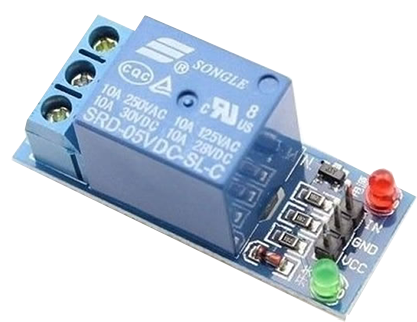
A relay module is a set of components that is electrically operated and works based on a signal. That can be connected to an Arduino or a transistor and or any other application that the output is a signal or a voltage. Same as relay the relay module is used to control high voltage electronic devices. A Relay module is a mechanical switch which is electrically operated by an electromagnet. When the electromagnet is activated with a low voltage, that can be 5 v, 12 v, 32 v, … it will triggers a mechanical arm that pulls a contact to make a connection between two contacts. Relay modules are used for high voltage controls, and big loads. Relay modules has low power lose in a circuit. In other hands they are slow and they are not quick as transistors.
Pin out of 5V relay module

Modes of connections:
- Normally open state (NO)
- Normally closed state (NC)
- Common
Normally open (NO)
In the normally open state, connections are open and do not allow current to pass through. And the initial output of the relay is low. In this state, the common and the normally open pins not connected unless relay is switched on.
Normally closed state (NC)
In the normally closed state, the connection are normally closed and both are connected to common pin and the initial output of the relay will is high when it is not powered. In this state, the common and the normally close pins are used.
Schematic:


Components Required: .

- 5 V Relay switch
- Transistor NPN BC547
- 470 Ohm Resistor
- Wire Terminal
- Diode IN4001
- Led
- Hook up wires
- Soldering Wire
- Soldering iron
Application Example usage:

Download softwares:
Fritzing
https://fritzing.org/download/
Circuit Wizard:
https://www.new-wave-concepts.com/pr/cw_files.html
Buy This product: